 | CONTENTS 1. Technical Specification
2. Safety Test
3. Cabinet Drawing
4. Software Errors
5. Diagnostic Flow Chart
6. Power Board P.C.B.
7. Interface Circuit Diagram
8. Circuit Diagram
9. Relay P.C.B.
10. Interface P.C.B.
11. Alignment Checks
12. MechanismSpecificationsHardware.The disc drive is a 3" system, conforming to the Hitachi/Panasonic standard. The software is configured for a 12mS step rate, and 30mS settling time.
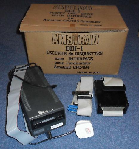
Each drive is supplied with its own integral mains power supply-which in the case of the first drive (DDI-1) also supplies power to the disc expansion interface via the interconnecting cable supplied.
The DDI-1 is supplied complete with plug-on interface controller and cable. The system is designed to control a maximum of 2 drives. Also housed in the interface is an expansion ROM, containing the extensions for AMSDOS and the machine dependant elements of CP/M and LOGO.
The ruggedly constructed 3" discs are usable on both sides, each side is provided with a reusable write protect clip which is slid into position as required.AMSDOS & CP/MAMSDOS is a disc operating system which expands Locomotive BASIC, adding additional commands to make full use of the disc files. AMSDOS enables BASIC programs to access disc files in the same manner as cassette files, in fact the same commands are used with file names conforming to CP/M conventions. AMSDOS and CP/M both share the same file structure and can read and write each other's files.
A version of the Digital Research CP/M operating system is supplied with the DDI-1, permitting the user to access the wealth of applications software written to run under CP/M. In addition to the usual CP/M utilities, additional features have been included for the CPC464.Disc Organisation:Both AMSDOS and CP/M support three different disc formats:
SYSTEM format, DATA only format, and IBM format.
Format selection is automatic on disc access. All three formats use the same framework, but have different sector configurations.
Common to all:
Single sided, double density.
512 byte sector size.
40 tracks.
Sectors interleaved 2:1.SYSTEM format:
The most frequently used format, since CP/M may only be loaded from a system format disc. 2K is used for the directory, and 9K reserved for the system.
9 sectors per track.
2 reserved tracks for CP/M.
169K byte file capacity.DATA only format:
All the tracks are used to store data.
2K bytes reserved for the directory.
9 sectors per track.
No reserved tracks.
178K byte file capacity.IBM format:
Logically similar to the single sided
format used by CP/M on the IBM PC.
2K bytes used for the directory, 4K
reserved.
8 sectors per track.
1 reserved track.
154K byte file capacity.
Either side of an AMSTRAD CP/M or AMSDOS disc may be accessed by the disc controller, depending on which way round the disc is inserted.
Disk Drive
Size: 75(H) x 105(W) x 280(D)mm
Weight: 1.6Kg
Voltage: 240V AC 50HzInterface Size: 75(H) x 165(W) x 35(D)mm
Weight: 0.2Kg
SAFETY TEST All units are safety tested to the following specifications.
1). Flash Test
Test at 3kV between the live and neutral of the mains lead joined together and
and ALL accessible metal points on the exterior of the set.
2). Insulation Resistance Test
Test between the live and neutral of the mains lead joined together and ALL accessible metal points on the exterior of the set to show a resistance of at least 4Mohm.
If after servicing there is any doubt about continued electrical safety the above tests should be carried out. |
AMSTRAD CONSUMER ELECTRONICS PLC
BRENTWOOD HOUSE, 169 KINGS ROAD, BRENTWOOD, ESSEX CM14 4EF.
Telephone: Brentwood (0277) 228888. Telex: 995417 AMSELE G.CABINET DRAWING  Software ErrorsIf a drive fault is reported the fault may be a software problem. Before investigating the drive please carry out the following checks to ensure it is not a software problem.Detection and Correction of "Soft Errors"
Soft errors are usually caused by the following reasons.
1) Random external noise of several usee or less.
2) Minute off-tracking and shifting of write timing that are not detected during the write operation which can cause the soft error during the read.
To remedy such soft errors, take the following procedures at the controller side.
1) Repetitive reading on the track by 10 times or more until the data is restored.
2) When the data is not restored by step 1, access the head to the adjacent track in the same direction as move previously, and thereafter return the head to the original track.
3) Repeat the step 1.
4) If the data is not restored by the above steps, the error cannot be remediedWrite ErrorWhen an error is caused during the write operation, the error is usually detected during the next rotation through the read operation called "Write check".
To correct the error, repeat the write operation again and carry out the Write check.
If the result is still incorrect even after the write operation is repeated more than 10 times, either the disc or the drive are working incorrectly. To find out the trouble source, carry out the read operations with another track. Should the error still be found, change the disk and repeat the above procedures. Should error still be found, the drive should be considered defective. If the error is removed, the original disk must be defective. Discard it.Seek Error
1) Step motor or step motor drive circuit is defective.
2) The torque of the carriage is not correct.
Restoration procedures from the seek error.
Make the re-calibration to the track OO. Then, carry out the re-seek to the original track.
Notes:
1) Always ensure the head is clean.
2) Index/Sector Factor (Ready Defect)
As the unit has Optional Read Output
It is normally not ready until 2 revolutions are made after the disk insertion.Diagnostic Flow ChartThis chart must be used in conjunction with
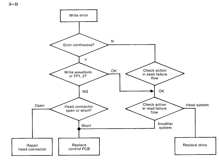
the Alignment Procedures. This chart is for information only and does not guarantee an exact diagnosis. For warranty purposes any faulty drive mechanism must be returned to Amstrad for replacement. Service Agents should not attempt any repairs on the mechanism or to its P.C.B. P.No. 30001.  FLOW CHART (cont) FLOW CHART (cont) 
 POWER BOARD P.C.B.
 INTERFACE CIRCUIT DIAGRAM

 RELAY P.C.B.
 
Only parts from the Power Supply and Interface are quoted. Parts are not available for PCB30001. Should this be faulty it must be returned complete with mechanism to AMSTRAD for exchange.F.D.I. P.C.B. INTERFERENCE BOARD The data contained in the following 5 pages is for information only. Service Agents must not carry out any repair or adjustment to the Drive mechanism and its associated PCB 30001 during warranty. Faulty mechanism must be returned to AMSTRAD for exchange.Alignment ChecksPlease use this this information in conjunction with the diagnostic flow chart.
Equipment required: Double Beam Scope; EME - CF2 Test Disk (please refer to disk notes for usage).
The following checks can be carried out in routine servicing. If the wave patterns do not appear this confirms a fault with the mechanism. Before attempting any replacement check these waveforms thoroughly.
+----------------------------------------------------------------+---------+
| Content of adjustment and checking ; | CE DISK |
| ; | EME CF2 |
+----------------------------------------------------------------+---------+
| 1. Radial adjustment by use of Track 19 (Fig. 1). ;| O |
| 2. Adjustment of the index burst by use of Track 39 (Fig. 2). | O |
| 3. Azimuth check by use of Track 39 (Fig. 3-4). ; | O |
+----------------------------------------------------------------+---------+List of Test Points
+------------+-------------------------------+
| Test point | Name of signal ; |
+------------+-------------------------------+
| TP 1 | Read signal of filter outlet |
| TP 2 | Read signal of filter outlet |
| TP 3 | Signal ground ; |
| TP 5 | TROO sensor output ; |
| TP 9 | Index signal ; |
| TP 11 | Signal ground ; |
+------------+-------------------------------+
Fig.1 Waveform of T19 (Servo pattern)
Fig. 2 Waveform of T39 (Index pattern - Radial alignment)
Fig. 3 Waveform of T39 (Azimuth, alignment)
Fig. 4 Waveform of T39ALIGNMENT CHECKS (cont)1) Check Positioning1) Load CE Disk.
2) Set up track OO, Motor off.
3) Scope to TP5.
4) Adjust OO Sensor (8 on Fig. 6) so that scope shows correct difference as Fig. 2.2) Adjustment of Index Timing1) Load the CE Disk (refer to disk info)
2) Step the disk to the track 39.
3) Synchronise the oscilloscope by TP9 (INDEX). Set the time base to 0.1 msec/DIV.
4) Connect the probe to TP1.
Connect the ground probe to TP3 and TP11 (ground) of PCB. Set the input to AC and set the vertical axis to 20mV/DIV.
5) Measure timing between sweep start and an initial data pulse. It should be 500 usee+500 usee. When the timing is not within this range, proceed with the following adjustment. (Refer to Fig. 5-1).
6) Loosen the two screws fixed LED printed board. Adjust the position of LED printed board so that the timing is 500 usee ± 100 usee.
7) Re-check the timing.
8) Seek to the track OO and make sure that the timing is within 500 usee + 200 usee. Tighten the screws. (Fig. 5-1).3) Check of Head OutputThis check is effective only when making write and read check as described below. If the output level is less than the prescribed output, clean the head before check. Disk used for this check must be in good condition.
1) Load the CE Disk.
2) Select track 39.
3) Connect one of the probes of the oscilloscope to TP1 of the printed circuit board, another probe to TP2, and the probe to ground to TP3, TP11 (ground).
Invert one channel, and set it to Add input, set input to AC, and set the vertical axis to 50mV/DIV and the horizontal axis to 20msec/DIV.
4) Make sure tha average output level is the following value or more: 140 mV p-p (SN 25dB or more) If the output is less than the above-described value, replace the head.4) Adjustment of Positioning1) Load CEdisk.
2) Select Track 19.
3) Monitor the output in the same way as the head output inspection.
Calculate the off-track amount in reference to the calibration graph, showing the interrelation between the burst amplitude ratio and off-track amount. (Refer to Fig. 5-2).
4) The average of amplitude ratio should be below 26 urn.
If it is not within this range, make the following adjustment.
i) Loosen the bolt of the rotation stopper which fixes the screw shaft (Fig. 6-3). Rotate the screw shaft and adjust it in such a way that the amplitude ratio may become below 15 uM. Tentatively set the bolt at that position.
ii) Make the to track step to the inner and outer circles and bring it to the original position. Make sure that the adjustment is all right. Then, tighten the bolt.
5) Confirmation of Head Azimuth
1) Load the CE Disk
2) Select Track 39.
3) Synchronise the probe of the oscilloscope by TP9 of PCB and connect another probe to TP1, and the probe ground toTP3, TP11 (ground). Set the input to AC, the vertical axis to 10mV/DIV, and the horizontal axis to 0.5 msec/DIV. Make sure that the two outside burst waveforms are smaller than two inside burst waveforms as shown in Fig. 5-3.
Note: Signal preceding the azimuth burst is the index burst. If the azimuth is still incorrect reeplace the head assembly. ALIGNMENT CHECKS

Fig. 5-1 Index burst waveform
Amount of Off-center (µ)Fig. 5-2 Off-centre calibration curve
(Effective width of read head is 180u) 
Fig. 5-3 Azimuth burst
Fig. 5-4 shows azimuth burst in the cases of azimuth -1 2', 0' and +1 2.MECHANISM
MECHANICAL REPLACEMENTS
Head Assembly
i) Remove 2 screws from F. panel and remove F. panel.
ii) Remove 4 screws from the control PCB.
iii) Disconnect plug from Stepper Motor.
iv) Disconnect plug from LED P.C.B.
v) Disconnect transistor from Spindle Motor.
vi) Disconnect Index Sensor from front of P.C.B.
vii) Raise P.C.B. from side opposite LED and remove plug from head.
viii) Control P.C.B. will now be free - remove.
ix) Remove 4 screws securing the Loading Unit to the chassis from the Flywheel side and remove
Loading Unit.
x) Remove spring and rod support screws.
xi) Gently slide the head off the rod.
xii) Replacement is reverse process.
After reassembly check alignment of Azimuth Burst/Track 00 Positioning.Spindle Motor
i) Remove transistor fitted to Motor,
ii) Unplug CN5 from Control P.C.B.
iii) Remove Drive Belt.
iv) Undo 2 screws securing motor.
v) Replacement is reversal of removal.
vi) Adjust VR201 so Index frequency is 200 ± 2ms (See Fig. 5-1).Stepper Motor
i) Remove Control P.C.B. as (1).
ii) Remove 2 securing screws for Stepper Motor Bracket.
iii) Stepper Motor can now be removed.
iv) After replacement index and positioning must be checked and amended as necessary.
| |
https://cpcrulez.fr
| ★ AMSTRAD CPC ★ DOWNLOAD ★ |
|
CPCrulez[Content Management System] v8.732-desktop/c
Page créée en 526 millisecondes et consultée 7530 foisL'Amstrad CPC est une machine 8 bits à base d'un Z80 à 4MHz. Le premier de la gamme fut le CPC 464 en 1984, équipé d'un lecteur de cassettes intégré il se plaçait en concurrent du Commodore C64 beaucoup plus compliqué à utiliser et plus cher. Ce fut un réel succès et sorti cette même années le CPC 664 équipé d'un lecteur de disquettes trois pouces intégré. Sa vie fut de courte durée puisqu'en 1985 il fut remplacé par le CPC 6128 qui était plus compact, plus soigné et surtout qui avait 128Ko de RAM au lieu de 64Ko. |
|
|
