


★ CODING ★ THE MIGHTY CRTC 6845 ★ |
| The mighty CRTC 6845 |
The mighty CRTC 6845 This chip generates the signals necessary to interface with a raster display (but it does not display any pixels-stuff itself) :
The HSync, VSync and DISPEN are two states signals (ON/OFF, 1/0 or high/low, you get the idea :) sent to the GateArray, which will read, every microsecond, two consecutive bytes in the base 64Kb RAM at the MA address. Then the Gate Array will produce all the video signals required by the monitor (Red, Green, Blue, HSync and VSync). The CRTC has a total of 18 8-bit registers controlling all aspects of the video timings. It's clock frequency on the Amstrad CPC/Plus is 1MHz (so the CRTC updates itself every microsecond). Four I/O ports are assigned to it :
There's at least five CRTC types known on the Amstrad CPC/Plus. All of them are based on the same design (originally by Motorola) but have a different implementation, introducing differents behaviours in some situations or provide specific features. These CRTC types were defined by Longshot from the Logon System in the early days of the CPC demoscene (1989/1991) and are still widely used at this time by demosceners.
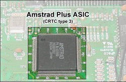
The CRTC Type 3 and 4 are CRTC emulated by an ASIC in the Plus and CPC respectively. These are not real chips soldered on the motherboard like the type 0,1 and 2 are. The type 4 has been manufactured in the very last CPC produced by Amstrad (to reduce the cost and probably to test this technology before the Plus range) and is less common, that's why it was discovered only after the type 3 (of the Amstrad Plus range) although it was released before.
I recently came across a CRTC from Hitachi which seems to be a type 0 but slightly differs in some contexts (I'm still studying this atm) from others type 0 I have, so there's maybe more than 5 CRTC types :) How it works To fully understand how to control the video output of the CPC, you have to know how the CRTC is working internally (and little knowledge of the Gate Array is recommended too for all the colors and graphics mode related stuff). So here it is, the key of the understanding of the CRTC is : it's just a bunch of counters and triggers!
Internal Registers Here are the 18 internal registers we can play with to affect the video-timings produced by the CRTC. Most of them are Write-Only (you can only set their value but not read it back), some of them are Read Only (eg. offset registers related to the lightpen) and finally, very few of them are Read/Write. But it depends on the CRTC type (We will see that later). Here are the 18 internal registers we can play with to affect the video-timings produced by the CRTC. Most of them are Write-Only (you can only set their value but not read it back), some of them are Read Only (eg. offset registers related to the lightpen) and finally, very few of them are Read/Write. But it depends on the CRTC type (We will see that later).
The defaults values given here are those programmed by the firmware ROM after a cold/warm boot of the CPC/Plus. Register-groups There's basically 3 register-groups:
A video frame is made of differents signals generated by the CRTC and Gate Array in order to produce something shiny (or not :) on the monitor. You can (almost) do whatever you want with the CRTC, really. However, if you expect to get something watchable on the monitor plugged to your CPC then your CRTC configuration must comply to some rules : the monitor timings! Very briefly, for a monitor to display a stable and clean image, it requires that the HSync and VSync signals from the CRTC/Gate Array are within it's allowed Horizontal and Vertical refresh-rate range. Otherwise, the monitor will, at best, display a distorted and/or rolling image and may also produce a weird high-pitched noise. That's why hacking with the CRTC is sometime confusing. You have to deal with two video devices at the same time: the CRTC iteself but also the monitor. Both having their own rules. So whatever you want to do with the screen, just keep it mind that their is a monitor behind and if you mess with the synchronization signals, the monitor won't like it. Monitor The standard monitors on the Amstrad (GT6x, CTM64x, CM14 or even TV) have a 50Hz Vertical refresh rate (meaning that a VSync pulse must appear every ~20ms, 19968μs exactly) and a 15625Hz Horizontal refresh rate (an HSync pulse every 64μs). Of course they can usually tolerate some slight variations of these timings but each monitor has it's own limitations. For exemple, some monitor will accept a 65Hz Vertical-refresh rate while some other will completly lose synchronization with anything above 50.2Hz vertical refresh-rate. So it's all about reliability. You're free to do weird timings, it may work on -your- monitor but you can be sure it won't work on all monitor. If you stick to the standard 50Hz/15625Hz refresh-rates, all (correctly working) monitors will do fine.
Here is an illustration of the output produced by the CRTC/GA after a warm/cold boot.
The CRTC can accessed by the CPU via 4 I/O address. CRTC's I/O decoding use A14, IORD and IORW signals to enable the CRTC (see the figure on the left). A9 and A8 are used to choose one of the 4 CRTC I/O operations (Select, Write, Status and Read register).
Standard I/O R/W indicate the type of I/O operation you should do, but nothing prevent you to read a write-only register. Doing so may produce unexpected results. &BC00 : Select register Z80 Assembler To select any of the CRTC registers from your Z80 program : ; select CRTC Register 6 (Vertical displayed character number)Since the I/O decoding design for the CRTC only use few bits of the MSB I/O address (see I/O decoding for more informations), you can save some CPU load and register by using the LSB of the I/O address to store the CRTC register index : | |||||||||||||||||||||||||||||||||||||||||||||||||||||||||||||||||||||||||||||||||||||||||||||||||||||||||||||||||||||||||||||||||||||||||||||||||||||||||||||||||||||||||||||||||||||||||||||||||||||||||||||||||||||||||||||||||||||||||||||||||||||||||||||||||||||||||||||||||||||||||||||||||||||||||||||||||||||||||||||||||||||||||||||||||||||||||||||||||||||||||||||||||||||||||||||||||||||||||||||||||||||||||||||||||||||||||||||||||||||||||||||||||||||||||||||||||||||||||||||||||||||||||||||||||||||||||||||||||||||||||||||||||||||||||||||||||||||||||||||||||||||||||||||||||||||||||||||||||||||||||||||||||||||||||||||||||||||||||||||||||||||||||||||||||||||||||||||||||||||||||||||||||||||||||||||||||||||||||||||||||||||||||||||||||||||||||||||||||||||||||||||||||||||||||||||||||||||||||||||||||||||||||||||||||||||||||||||||||||||||||||||||||||||||||||||||||||||||||||||||||||||||||||||||||||||||||||||||||||||||||||||||||||||||||||||||||||||||||||||||||||||||||||||||||||||||||||||||||||||||
| Type 0,1,2,3 and 4 | |||||||||
|---|---|---|---|---|---|---|---|---|---|
| I/O Address | Function | Data bits 7 to 0 | |||||||
| &BC00 | Select reg. | x | x | x | d | d | d | d | d |
This CRTC function allow to change the value of any writable CRTC registers. A Write command on a read only (or unused) CRTC register will have no effect.
Z80 Assembler
Once you've selected a CRTC register, you can change it's value by writing it at the I/O address &BD00 :
To do the same thing from the Locomotive BASIC interpreter :
Writable CRTC registers table
| Type 0 | Type 1 | Type 2 | Type 3 | Type 4 | ||||||||||||||||||||||||||||||||||||||||||
|---|---|---|---|---|---|---|---|---|---|---|---|---|---|---|---|---|---|---|---|---|---|---|---|---|---|---|---|---|---|---|---|---|---|---|---|---|---|---|---|---|---|---|---|---|---|---|
| Reg | Description | Unit | Data bits 7 to 0 | Data bits 7 to 0 | Data bits 7 to 0 | Data bits 7 to 0 | Data bits 7 to 0 | |||||||||||||||||||||||||||||||||||||||
| R0 | Horizontal total character number | char | d | d | d | d | d | d | d | d | d | d | d | d | d | d | d | d | d | d | d | d | d | d | d | d | d | d | d | d | d | d | d | d | d | d | d | d | d | d | d | d | ||||
| R1 | Horizontal displayed character number | char | d | d | d | d | d | d | d | d | d | d | d | d | d | d | d | d | d | d | d | d | d | d | d | d | d | d | d | d | d | d | d | d | d | d | d | d | d | d | d | d | ||||
| R2 | Position of horizontal sync. pulse | char | d | d | d | d | d | d | d | d | d | d | d | d | d | d | d | d | d | d | d | d | d | d | d | d | d | d | d | d | d | d | d | d | d | d | d | d | d | d | d | d | ||||
| R3 | Width of horizontal/vertical sync. pulses | char | V4 | H3 | H2 | H1 | H0 | H3 | H2 | H1 | H0 | H3 | H2 | H1 | H0 | V3 | ? | ? | H3 | H2 | H1 | H0 | V3 | H3 | H2 | H1 | H0 | |||||||||||||||||||
| R4 | Vertical total Line character number | char | d | d | d | d | d | d | d | d | d | d | d | d | d | d | d | d | d | d | d | d | d | d | d | d | d | d | d | d | d | d | d | d | d | d | d | |||||||||
| R5 | Vertical raster adjust | line | d | d | d | d | d | d | d | d | d | d | d | d | d | d | d | d | d | d | d | d | d | d | d | d | d | |||||||||||||||||||
| R6 | Vertical displayed character number | char | d | d | d | d | d | d | d | d | d | d | d | d | d | d | d | d | d | d | d | d | d | d | d | d | d | d | d | d | d | d | d | d | d | |||||||||||
| R7 | Position of vertical sync. pulse | char | d | d | d | d | d | d | d | d | d | d | d | d | d | d | d | d | d | d | d | d | d | d | d | d | d | d | d | d | d | d | d | d | d | |||||||||||
| R8 | Interlaced mode | d | d | U1 | U0 | C | D | T | RC | I1 | I0 | I1 | I0 | C1 | C0 | D1 | D0 | I1 | I0 | d | d | |||||||||||||||||||||||||
| R9 | Maximum raster | line | d | d | d | d | d | d | d | d | d | d | d | d | d | d | d | d | d | d | d | d | d | d | d | d | d | |||||||||||||||||||
| R10 | Cursor start raster | line | d | d | d | d | d | B1 | B0 | d | d | d | d | d | B | P | d | d | d | d | d | d | d | d | d | d | d | d | d | d | d | |||||||||||||||
| R11 | Cursor end | line | d | d | d | d | d | d | d | d | d | d | d | d | d | d | d | d | d | d | d | d | d | d | d | d | d | |||||||||||||||||||
| R12 | Display Start Address (High) | d | d | d | d | d | d | d | d | d | d | d | d | d | d | d | d | d | d | d | d | d | d | d | d | d | d | d | d | d | d | |||||||||||||||
| R13 | Display Start Address (Low) | d | d | d | d | d | d | d | d | d | d | d | d | d | d | d | d | d | d | d | d | d | d | d | d | d | d | d | d | d | d | d | d | d | d | d | d | d | d | d | d | |||||
| R14 | Cursor Address (High) | d | d | d | d | d | d | d | d | d | d | d | d | d | d | d | d | d | d | d | d | d | d | d | d | d | d | d | d | d | d | |||||||||||||||
| R15 | Cursor Address (Low) | d | d | d | d | d | d | d | d | d | d | d | d | d | d | d | d | d | d | d | d | d | d | d | d | d | d | d | d | d | d | d | d | d | d | d | d | d | d | d | d | |||||
Because of the I/O decoding design, if you perform a CPU I/O read instruction (IN, INI, etc) on this I/O address, the CPU will expect the CRTC to provide a value on the DATA bus, but it won't because it just don't care if it's a Read or Write CPU I/O operation. As soon as an active I/O request (Read or Write) is active on the Write Register I/O address (&BD00), the CRTC will read whatever is on the data bus and write it into the currently selected CRTC register. In this case, the DATA bus will be in high impedance state while the CRTC will read it. The value read on the DATA bus while it is in high impedance state is UNPREDICTABLE, it can be any value from 0 to 255, vary over the time, electrical conditions and/or the peripherals connected to the CPC/Plus!
&BE00 : Status Register
WARNING: The status register provide 3 informations flags :
U (bit 7) : Update Ready
The following table shows what data you get if you read this register on the various CRTC type.
| Type 0 | Type 1 | Type 2 | Type 3 | Type 4 | ||||||||||||||||||||||||||||||||||||||||||
|---|---|---|---|---|---|---|---|---|---|---|---|---|---|---|---|---|---|---|---|---|---|---|---|---|---|---|---|---|---|---|---|---|---|---|---|---|---|---|---|---|---|---|---|---|---|---|
| I/O Address | I/O R/W | Function | Data bits 7 to 0 | Data bits 7 to 0 | Data bits 7 to 0 | Data bits 7 to 0 | Data bits 7 to 0 | |||||||||||||||||||||||||||||||||||||||
| &BE00 | Read | Status reg. | z | z | z | z | z | z | z | z | U | L | V | 0 | 0 | 0 | 0 | 0 | z | z | z | z | z | z | z | z | d | d | d | d | d | d | d | d | d | d | d | d | d | d | d | d | ||||
&BF00 : Read register
Readable CRTC registers table
| Type 0 | Type 1 | Type 2 | Type 3 | Type 4 | ||||||||||||||||||||||||||||||||||||||||||
|---|---|---|---|---|---|---|---|---|---|---|---|---|---|---|---|---|---|---|---|---|---|---|---|---|---|---|---|---|---|---|---|---|---|---|---|---|---|---|---|---|---|---|---|---|---|---|
| Reg | Description | Unit | Data bits 7 to 0 | Data bits 7 to 0 | Data bits 7 to 0 | Data bits 7 to 0 | Data bits 7 to 0 | |||||||||||||||||||||||||||||||||||||||
| R10 | Cursor start raster | line | d | d | d | d | d | B1 | B0 | d | d | d | d | d | B | P | d | d | d | d | d | d | d | d | d | d | d | d | d | d | d | |||||||||||||||
| R11 | Cursor end | line | d | d | d | d | d | d | d | d | d | d | d | d | d | d | d | d | d | d | d | d | d | d | d | d | d | |||||||||||||||||||
| R12 | Display Start Address (High) | d | d | d | d | d | d | 0 | 0 | 0 | 0 | 0 | 0 | 0 | 0 | 0 | 0 | 0 | 0 | 0 | 0 | 0 | 0 | d | d | d | d | d | d | d | d | d | d | d | d | |||||||||||
| R13 | Display Start Address (Low) | d | d | d | d | d | d | d | d | 0 | 0 | 0 | 0 | 0 | 0 | 0 | 0 | 0 | 0 | 0 | 0 | 0 | 0 | 0 | 0 | d | d | d | d | d | d | d | d | d | d | d | d | d | d | d | d | |||||
| R14 | Cursor Address (High) | d | d | d | d | d | d | d | d | d | d | d | d | d | d | d | d | d | d | d | d | d | d | d | d | d | d | d | d | d | d | |||||||||||||||
| R15 | Cursor Address (Low) | d | d | d | d | d | d | d | d | d | d | d | d | d | d | d | d | d | d | d | d | d | d | d | d | d | d | d | d | d | d | d | d | d | d | d | d | d | d | d | d | |||||
| R16 | Light Pen Address (High) | d | d | d | d | d | d | d | d | d | d | d | d | d | d | d | d | d | d | d | d | d | d | d | d | d | d | d | d | d | d | |||||||||||||||
| R17 | Light Pen Address (Low) | d | d | d | d | d | d | d | d | d | d | d | d | d | d | d | d | d | d | d | d | d | d | d | d | d | d | d | d | d | d | d | d | d | d | d | d | d | d | d | d | |||||
Differences between models
Memory Address (MA)
The MA is reloaded with the value from R12 and R13 when VCC=0 and VLC=0 (that's when a new CRTC screen begin). However, CRTC Type 1 keep updating the MA on every new scanline while VCC=0 (and VLC=<R9).
Interlaced video-mode (R8)
The CRTC 6845 can be programmed, via it's register R8, to handle different video mode, interlaced or not interlaced. Unfortunately, this feature is by far the most bugged and very badly supported amongs the various CRTC type found on the Amstrad CPC/Plus, none of them is able to produce a proper interlaced mode! To keep the doc as simple as possible, I will simply skip the details about the interlaced features (for now), it's barely useful and higly incompatible between CRTC type anyway. If you want to read more informations about this feature, I suggest you take a look at the datasheet at the end of this page, switch ON your CPC and do some tests :)
Programming the CRTC 6845
REMEMBER: Be monitor friendly
No matter what you are doing with the CRTC, from setting up a simple fullscreen to any complex split-screen frame structure, to keep friendly with the monitor :
Simple screen configuration
For advanced timings and electricals informations on the CRTC, check these datasheets.
Pictures
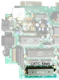
Picture of a Motorola CRTC 6845P (type 2).
|


