| ★ HARDWARE ★ MONTAGES ★ CPC 464 PLUS MEMORY UPGRADE (AMSTRAD ACTION) ★ |
CPC 464 Plus Memory Upgrade (1/2) (Amstrad Action) | CPC 464 Plus Memory Upgrade (2/2) (Amstrad Action) |
Of all the great add-ons for the 464 Plus the most popular are the 64K RAM pack and the disk drive. They're also the most expensive... or are they? In the first part of a new series, PHIL CRAVEN tells you how to cut the cost of add-ons. A RAM pack costs between forty and fifty pounds, and a disk drive about £160. There's nc doubting their usefulness but there's no doubting their cost either. So what if I were to tell you that you could have the extra 64K for only a tenner? You like that? And how about knocking, say, fifty to sixty quid off the cost of a drive? You like that too? Aaw, shucks. Sad to say, it can't be done. I'm sorry to be the one to tell you but, although we can get you the drive for a tweak over £100, the best we can manage the extra 64K for is £10.72, including VAT and postage, which is a massive 72p up on what I led you to think. You still want it? Oh, all right. If you've got money to burn, read on.
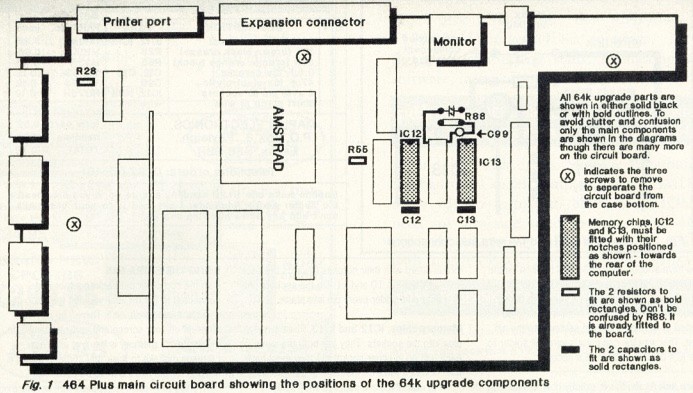
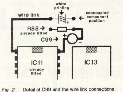
Until you actually buy one, you wouldn't know that the existing 64K RAM pack was designed to perch neatly on the back of the older 464 and, although it works fine on the 464 Plus, it doesn't exactly perch neatly anywhere. In fact it fits rather like a square peg in a round hole, and I don't just mean that they have different connectors. The RAM pack is too tall for the 464 Plus. The answer to this is to either raise the computer on a board or use an extension cable and let the RAM pack sort of flop all over the desk. The best solution is not to use the RAM pack at all but to put the extra 64K inside the computer where it couldn't be neater. Using a soldering iron, a solder sucker and this article you can upgrade your 464 Plus to 128K, the same as the 6128 Plus, and, because the parts cost a mere £10.72, you can save yourself at least £30 in the process! It isn't widely known, but the main circuit boards of the 464 Plus and the 6128 Plus are identical, having identical circuit tracks and identical holes for the various components. The difference between the two models is that the 6128 Plus has the disk interface and extra 64K components fitted where the 464 Plus has holes and the 464 Plus has tape components fitted where the 6128 Plus has holes. So it doesn't take an Einstein to wonder if putting the extra 64k components into the correct holes in the 464 Plus' circuit board would produce a 128K computer - and it does! The same applies with the disk interface components (464 Plus) and the tape interface components (6128 Plus). But first - the extra 64K. Assembling the upgrade kit is simple. There are ten components to buy and fit (see the parts list) but, before you rush to get them, take a little time to examine the task ahead and make sure that you are confident enough to perform it or that you know a man who is. With all power turned off, remove all peripherals including the cartridge and tape from the computer and disconnect it from the monitor. Turn the computer upside down and remove all the screws from the underside. While you've got the underside up, notice the three catches - one in the centre of the front and one on each side. Turn the keyboard the right way up again and, with your fingers, undo the three catches. The front one pulls towards you and the side ones pull outwards. That done, press EJECT on the tape player to raise its lid and lift the top of the casing away from the keyboard. It will fold back but it is still connected to the circuit board by several wires so don't yank at it. Whilst you're doing the job, the circuit board will be completely removed from the computer but, at this point, leave it where it is and leave the top connected to it. Don't touch anything on the circuit board but compare it with Fig.1 and Fig.2 and take a little time to consider how the 64K upgrade will be done. Fig.1 shows where the components are fitted to the circuit board, Fig.2 shows the detail of fitting the electrolytic capacitor and wire link and the parts list indicates each component that you will have to fit. Use the diagrams to identify the location where each component fits. You will notice that the holes for the components have been filled with solder during the manufacturing process and it needs to be removed before fitting the components. For that, you'll need a solder sucker. Tandy sell a cheap bulb-type one that looks like abit like a small vinegar bottle and Maplin sell a better one called a Desolder Tool - its order code is FR26D and it costs £3.95. If it looks easy enough to you then go ahead and buy the parts. If not, then close up the computer in the reverse order to opening it and consider the service offered by Avatar. DOING IT Open the computer as described earlier. Now, before going any further, hold your cold water tap for a second to discharge any static electricity from your body. That done that, touch the circuit board and chips as little as possible. Zapping a chip with the body's static electricity is rare these days but it's always better to err on the side of caution. Remove the case top from the circuit board by disconnecting the wires that join them. Notice that the the two pairs of wires have colour-coded sockets - the blue socket goes on to the blue plug and the black one on to the black plug. Those plugs and sockets clip together and a small screwdriver is needed to prise their vertical tongues slightly open. Remove the tape deck connector by pulling it upwards. Remove the keyboard by pulling the two film connectors from their sockets and take out the three screws that hold the circuit board to the case bottom (see Fig.1). The circuit board can now be lifted out but handle it by its edges. The component's pins on the underside of the board are sharp and will scratch a polished surface. You have been warned, you've no excuse. Suck the solder from the holes that are needed for the ten components. You'll probably find it easier to suck from the underside of the board. Don't worry about the weight of the board bending the copper leaf springs. They will bend back again later. With the solder sucker poised very near a hole melt the solder inside the hole with your soldering iron, quickly move the sucker nozzle onto the hole and suck. Some of the holes will only be partly filled and sucking is more successful when a hole is full so, if at first you don't succeed, fill it up with solder and try again. It's easy when you get the hang of it. When all the holes have been cleared look closely at them, preferably with a magnifying glass, and get rid of any solder bits. Now you're almost finished! There is no particular order in which the components should be fitted but, to help you get used to it, you might like to do resistors R28 and R55 first. The only fiddly bits are the wire link and the electrolytic capacitor, C99, which are best fitted before the IC sockets. Otherwise the sockets can get in the way. FITTING EACH COMPONENT Resistors R28 and R55 To make buying the parts easier, I have specified them all from a single source, Maplin. But Maplin don't stock the precise resistors that Amstrad used in the 6128 Plus machines (l/6th watt, 4.1mm long). To avoid any possibility of overheating the resistors, the ones specified are 6.8mm long and are bigger than those already in the circuit board. This is not a problem. Bend the wires to fit the holes and solder into place. They are coded by coloured bands as shown in the parts list followed by a brown and a red band. Be sure to put the correct resistor into the correct place. It doesn't matter which way round they are fitted. Push the wires of one resistor through its holes so that the resistor's body is quite close to the circuit board and bend the wires outwards on the underside of the board. That prevents the resistor from slipping out when you turn the board over to solder it into place. Turn the board over and solder the wires into place. Trim off the excess wire. Now do the same with the other resistor. Capacitors CI2 and CI3 These are brown discs. Like the resistors, they can be fitted any way round - either wire in either hole. Electrolytic capacitor C99 There are no holes for this one and when you've fitted it, you'll think it looks a bit odd but, surprisingly, this is exactly how it is done in the 6128 Plus. C99 is a small metal can with two wires at one end and a dark stripe down one side, next to one of the wires. The stripe indicates that that wire is negative. It is important to connect this capacitor the correct way round. Fig.2 shows it as a circle with a positive sign (+) at one side and a negative sign (-) at the other. The negative sign indicates the dark stripe side. Melt a small blob of solder onto pin 18 of the existing memory chip, IC11, and solder C99's positive wire (not the dark stripe side) to that pin. Solder the negative wire to the side of the existing resistor, R88, as shown in Fig.2. You'll need to bend the wires to fit and the result will leave the capacitor sticking up but it can be bent over a bit before you close up the computer. When soldering to an 1C pin, as in this case, you have about six seconds with the iron on the pin before the heat starts to become dangerous for the chip. Six seconds is a very long time in soldering terms but, even so, it is best to do it as stated by melting a blob of solder onto the pin first. That way the capacitor's wire will solder to the IC's pin in a fraction of a second. Wire link Again, this is exactly how it is done in the 6128 Plus. Any short piece of wire will do. Strip about 1/8' of insulation from each end of the wire and tin the exposed metal conductors. Tinning is covering the conductor with solder and it is done by holding the soldering iron onto the conductor and allowing solder to melt over it. Melt a blob of solder onto pin 1 of the existing memory chip, IC11, and solder one end of the wire onto it. Solder the other end of the wire to the hole as shown in Fig. 2. It isn't necessary to clear that hole of solder as melting it will allow the wire to push through. Sockets for IC12 and IC13 These aren't really necessary but many people are afraid to solder the pins of chips. The sockets avoid that and they are cheap enough. Memory chips, IC12 and IC13 These simply plug into ttie sockets. They are both the same so each can go in either socket but they must have their notches towards the back of the computer. Most new chips are supplied with 'splayed' pins which must be bent inwards. It's quick and easy to hold a chip at each end with one row of pins on a hard surface and push down so that the whole row of pins bends inwards. You want each row to be more or less at right angles to the chip's body. Push each chip into one of the sockets making sure that all the pins go in and none become bent. CLOSING UP The upgrade is now finished and the extra memory can be used but, before closing up the computer, check that you have C99 the right way round and that the memory chips have their notches at the back. Now you can close it up, remembering to screw the circuit board to the case bottom and reconnect the keyboard's two film connectors, the tape connector and the blue and black wire pairs. The copper leaf springs should rest on the underside of the keyboard. If they have been bent down and can't touch the keyboard, bend them up again so that they do. USING THE EXTRA 64K With the computer put back together and connected to the monitor you can turn it on et voila! Nothing! Nowt! Zilch! There'll be nothing different on your screen and nothing to indicate that the extra memory is there at all. It's a common mistake to think that some software is needed for the extra 64K to be used. The DKTronics RAM pack is supplied with software which people imagine is necessary, but it isn't. What it does is test the extra memory and provide some RSX's so that it can be used from within Basic programs. But the main use of the extra 64K is with commercial programs that are written to use it and those programs will find it straight away. You don't have to do anything. You don't have to tell the computer that it's there and you don't have to tell a program that it's there. Programs that want it will find it. CPM+ is one such program. Using the extra memory in your own BASIC and machine code programs needs some knowledge of the CPC's memory organisation facilities which, unfortunately, is beyond the scope of this article. FINALLY DIY projects that tell you how to alter the insides of your computer are unusual and we don't want to leave you in the lurch so we have taken the unusual step of providing technical help for this project on a special phoneline - the number is 0274 602180. It must be said. If these instructions are followed accurately, and the parts are good, the upgrade will work. But we cannot control what a person does inside his/her computer and neither Amstrad Action nor Future Publishing, nor the author of this article can accept any responsibility or liability for any damage to parts or equipment that might occur by doing this project. I can say is that many others have already done the project as sold in kit form by Avatar. Hopefully, you've read this far before closing your computer so wet your appetite a bit by spotting another group of unused holes on the circuit board, including a set behind the tape deck that is obviously for a connector. A disk drive connector? You'll just have to wait and see, won't you? Seeya next month. AA PARTS LIST
|
|  |
|